
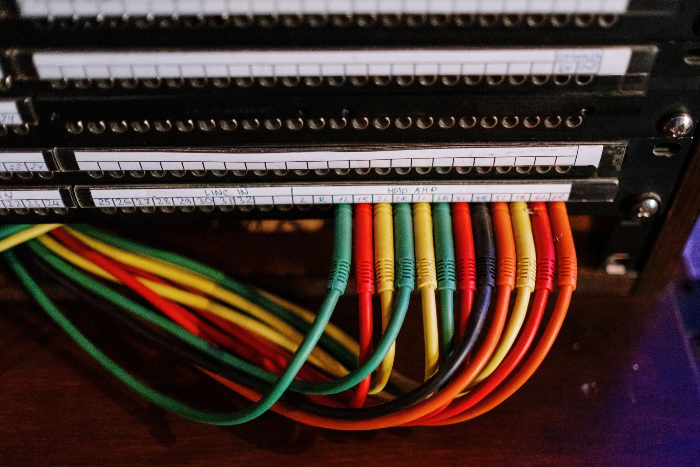
How to Set Up a Studio Patch Bay: First Cable to Full Recall
The patch bay is where your studio lives
Every studio has a signal-flow diagram, even if it only exists in the engineer's head. The patch bay is where that diagram turns physical. Mic lines, converter channels, console inserts and every piece of outboard meet on one panel, and every routing decision in a session goes through it.
We'll start with levels and normalling, work up through layout, inserts and hybrid DAW routing, then get into what a traditional TT bay costs you over time and how a relay-based bay like the Wolff Audio ProPatch handles the same jobs.
What is a patch bay and what is it used for?
A patch bay (or patchbay) is a panel that brings the inputs and outputs of every device in a studio to one place, so you can reroute signal with short patch cables instead of reaching behind racks. Each patch point is a pair of jacks: the top jack is usually a device's output and the bottom jack is the input it feeds. With normalling, signal flows from top to bottom with nothing plugged in, and a patch cable overrides or splits that default path.
Engineers use patch bays to insert outboard into a channel, change the order of a processing chain, split one source to several destinations, and switch the room between tracking and mixing setups.
The basics: levels, connectors and the patch point
A patch bay is only as good as its rules, and rule one is knowing what kind of signal lives on every jack. Put two different levels on the same row without labels and sooner or later someone patches a mic line into a +4 input and wonders where the signal went.
Signal levels on a patch bay
| Signal | Typical level | Where it lives on a bay | Watch out for |
| Mic | roughly -60 to -20 dBu | Tie lines from the live room to preamps | Phantom power on the line when you patch |
| Instrument / Hi-Z | unbalanced, high impedance | DI and re-amp points only | Loading and tone loss on long runs |
| Consumer line | -10 dBV (0.316 V) | Semi-pro synths, effects, some converters | About 12 dB lower than pro line |
| Pro line | +4 dBu (1.228 V) | Preamp outs, converters, console, outboard | The bulk of any bay |
| Digital (AES3) | 110 ohm balanced | Digital outboard and converter AES I/O | Impedance mismatches on long patch runs |
| MIDI / CV | control, not audio | Synth and modular rooms | Keep off audio rows so nobody mixes them up |
| Speaker level | amplified | Never on a patch bay | Shorting an amp output through a patch cable |
TT (Bantam) vs 1/4" TRS patch bays
TT bays win on density: 96 jacks, or 48 patch points, fit in a single rack space. Quarter-inch TRS bays hold about half that and take a sturdier plug, which is why some tracking rooms keep them. Watch the gauge, though. Old long-frame (B-gauge) jacks and standard TRS phone plugs have different tip profiles, and forcing one into the other wears out the springs.
DB25 wiring: Tascam (AES59) vs Yamaha pinout
Around back, most modern bays terminate on DB25 connectors carrying eight balanced channels each. The Tascam layout is standardized as AES59, and Yamaha uses a different pinout, so check which one your converters and console use before you order snakes.
Balanced wiring and the patch point
On TRS and TT, tip is hot, ring is cold and sleeve is shield. Keep the whole bay balanced and deal with unbalanced gear at the rear connection instead of with adapter cables on the front.
One patch point is a vertical pair of jacks, and nearly every studio follows the same convention: outputs on the top row, inputs on the bottom. Signal falls down the bay from a source above to its destination below. Stick to that and anyone can walk into your room and patch without a map.
Normalling: full-normal vs half-normal vs isolated
Normalling decides what a patch point does with nothing plugged in, and what breaks when something is. A full-normalled point connects top to bottom until you plug into either jack. A half-normalled point also connects top to bottom, but plugging into the top jack takes a copy without breaking the path, and only the bottom jack breaks it. An isolated point has no connection at all. Set it up well and the room runs with zero cables in the bay. Set it up badly and every session starts with a fistful of them.
| Mode | With nothing patched | Plug into top (output) | Plug into bottom (input) | Best used for |
| Full-normal | Top feeds bottom | Breaks the normal | Breaks the normal | Mic ties to preamps, points you rarely tap |
| Half-normal | Top feeds bottom | Taps the signal, normal stays intact | Breaks the normal | Insert sends/returns, direct outs to converters, anything you want to split |
| Isolated (open) | Nothing connected | Output only | Input only | Outboard ins and outs, tie lines |
| Parallel (bussed) | All jacks tied together | Nothing breaks | Nothing breaks | Passive mults |
Half-normal is the workhorse. It lets you pull a copy of a signal from the top jack without interrupting the path, which is how you send a snare to a parallel compressor while the dry snare keeps going to tape. Full-normal suits paths you only ever replace and never split. Outboard goes on isolated points, because a compressor's output should never be quietly feeding something you forgot about.
Two details catch experienced engineers. Grounds can be normalled too: many bays let you tie or lift the sleeve between top and bottom, and that choice shows up later as hum or silence. And every normal is a spring contact sitting in the signal path whenever nothing is patched, so the more normals a signal crosses, the more contacts it depends on. We'll come back to that.
How to set up and lay out a studio patch bay
Lay the bay out like the signal-flow diagram it replaces, left to right in the order sound moves through the room, and plan it on paper before you solder anything.
- Inventory every I/O. List every mic tie, preamp out, converter channel, console insert and bus, plus every input and output on every outboard box. Count stereo units as two.
- Group by stage, in signal order. A common sequence is live room ties, preamp outs, converter ins, converter outs, console channel inputs and inserts, buses, outboard, then monitoring. Reading the bay left to right should mean following the signal.
- Keep stereo pairs adjacent. Left on an odd point, right on the next even point, every time.
- Decide normalling per point, not per row. Use the table above and write the mode next to each point on your plan.
- Leave spares. Rooms grow. Leave blank points at the end of each group so a new compressor doesn't force you to rewire the whole bay.
- Label for the next engineer. Color-code groups, keep abbreviations consistent, and mark normalled points so a visitor can see what breaks what.
- Document the back. Keep a spreadsheet of which DB25 carries which channels. You'll want it at midnight when you're chasing a dead channel.
This is real work. A medium-sized room can mean hundreds of solder joints or crimped pins, and once it's wired the plan is basically frozen. Any later change means pulling snakes and relabeling.
Intermediate moves: inserts, mults and chains
Once the bay is wired, its value comes from how fast you can reshape signal flow in the middle of a session. These are the everyday moves.
Insert points
Console and converter inserts are usually half-normalled, send over return. Patch the send (top) into a compressor input and the compressor output into the return (bottom), and the box is in the channel. Tap the send on its own and you get a pre-insert copy without breaking anything.
Mults
A parallel-wired row turns one output into several, so you can split a bass DI to two amps or send a vocal to three processors at once. Mult one output to many inputs. Never tie several outputs into one jack, because the drivers fight each other and you get distortion or worse.
Parallel processing
Half-normal plus a mult is the classic recipe. The dry signal passes through untouched while a copy hits a crushed compressor that comes back on its own console channel or converter input. In analog there's no latency to manage, only level and polarity.
Reordering a chain
EQ into compressor sounds different from compressor into EQ. On a TT bay, swapping them means pulling and re-seating at least four cables, re-checking levels and remembering which was which. It's a small job once. It's a tax every time you want to try the alternative.
Staying at unity
Every box in a chain should sit near unity gain at +4 dBu unless you mean otherwise. If a chain creeps up 3 dB at each stage, your ears will pick the loudest option instead of the best one.
Advanced: hybrid rooms, re-amping, summing and grounding
Most rooms are hybrids now, and that's where patching gets interesting. It's also where the bay turns into the bottleneck.
Hardware inserts in the DAW
Put converter outputs on the top row and converter inputs on the bottom, then use any outboard box as a plug-in through your DAW's hardware insert (Pro Tools Hardware Insert, Logic's I/O plug-in, Ableton's External Audio Effect). Ping each insert for round-trip latency so delay compensation keeps it phase-aligned with the dry tracks, and match send and return levels so you're comparing tone rather than volume.
Re-amping
A line-level DAW output isn't a guitar pickup. Run it through a re-amp box to drop the level and raise the source impedance before it hits the amp, and keep that path on its own labeled points so nobody patches a +4 output straight into a pedal.
Summing and stems
Analog summing means eight, sixteen or more converter outputs feeding a summing mixer and then back into the converters. Put the summing inputs on a contiguous run of bottom-row points, half-normalled from the converter outs. That way the default is summing, and you can still pull any stem out for its own processing.
M/S and parallel buses
Mid-side matrices, parallel bus compression and stem processing all multiply the patch count. A full mix-bus chain with a parallel return can easily run ten or more cables, and every one of them has to be put back exactly for a recall.
Patch bay hum and ground loops
Most bay hum comes from ground loops, not from the bay itself. Keep the shield connected at one end on long runs where needed, watch for pin-1 problems in gear with poor chassis grounding, and decide on purpose whether sleeves are tied between top and bottom. If hum shows up on one particular patch, the ground path through that patch is the first thing to check.
Mic lines and phantom power
Patching a live mic line with phantom on can cause loud pops, and with ribbon mics it's a real risk. Standard practice is to mute or switch off phantom before you touch any mic-level patch.
Where manual patching breaks down
Everything above works, and studios have made great records on TT bays for decades. But a traditional bay has costs that grow with the room, and most engineers have stopped noticing them.
The first is the contacts themselves. Every jack and every normal is a spring contact. Over thousands of insertions the springs lose tension, and in between they oxidize. You know the symptoms: crackle when someone touches a cable, one side of a stereo pair sitting a little low, a channel that works until someone bumps the bay. Burnishing tools and contact cleaner become part of routine maintenance.
Does a patch bay degrade sound quality?
A clean, well-built patch bay shouldn't. Sound On Sound's Hugh Robjohns makes the point that professional studios routinely route signals through several patchbay sockets without problems, and that the real risk is tarnished or corroded connectors, which can produce low-level distortion in some cases. That's the catch with spring contacts: their condition changes over time, and a signal that crosses a normalled point, a patch cable and another normal depends on several of them in series.
Bainz noticed a difference when those contacts came out of his path after switching to ProPatch: "We immediately had more headroom, at least half a dB, and a level of clarity and balance that translated across the lows."
Recall, changing your mind and unused gear
Recall is manual. A patch only exists on the front of the bay, so getting it back next week means photos, patch sheets or memory, and one missed cable changes the mix.
Changing your mind gets expensive. Reordering a chain or auditioning three compressors on a vocal means re-patching, re-leveling and trying to remember what the last one sounded like. As Bob Horn put it: "You're not going to do that with a traditional patchbay. You're just not."
That friction has a quieter cost: the outboard that's hardest to patch is the outboard that sits cold. "A recording session is full of tons of cables, and it just gets cumbersome," Horn says.
Then there's plain human error. A wrong jack, a forgotten cable, phantom on a line that shouldn't have it, a mult that turned into an output tie. Each one is a physical action, and each physical action is a chance to get it wrong.
ProPatch: a software-controlled analog patchbay
If you've been searching for a "digital patchbay," this is the category, with one difference that matters: the audio path in ProPatch stays analog. The Wolff Audio ProPatch replaces spring jacks and front-panel cables with a grid of latching relays you control from a web browser. You wire every input and output in the room to it once, on DB25s at the back. After that, routing is a software decision.
There's nothing in the signal path except the relays. ProPatch uses a relay-based, software-controlled switching architecture with no buffers, amplifiers or active electronics in the path. Each connection is a telecom-grade relay contact built for millions of cycles. It passes line level, mic level with phantom power, digital audio, MIDI and control voltage. The relays latch, so routing holds through a power loss and presets come back on startup. It's fanless, so it can live in the control room without adding noise.
The browser app runs over USB-C or Ethernet and treats every box in the room as a node. You drag a source into a chain, drop processors in behind it in whatever order you want, and send it to a destination. To audition compressors against each other, you build an A/B group and switch with a click. The software also warns you about hardware conflicts, documents the routing and saves any setup as a preset. Owners can register the unit and download the control software from the ProPatch support page.
Routing that lives in software does mean you reach for a browser instead of a cable for anything wired through the back. For the things that change every day, like a borrowed synth, a guest's pedal or a laptop, every model has 16 TT points plus 4 XLR/TRS jacks on the front.
| Task | Traditional TT bay | ProPatch |
| Swap EQ and compressor order | Pull and re-seat four or more cables, re-check levels | Drag a node in the chain |
| Audition three vocal compressors | Re-patch each one, compare from memory | One A/B group, switch with a click |
| Recall last week's mix routing | Photos, patch sheets, memory | Load the preset |
| Switch from mix setup to tracking setup | Re-patch the room | Load a different preset |
| Contacts in the signal path | Spring jacks and normals that wear and oxidize | One relay contact per connection, no electronics |
| Power loss | Cables stay where they are | Latching relays hold the routing |
| Documentation | Your spreadsheet | Built into the software |
| Quick one-off patch | Cable on the front | 16 TT and 4 XLR/TRS on the front |
"It makes outboard gear feel like working with plug-ins, except you actually get to put your hands on it and turn the knobs." Bob Horn
"The connections on the ProPatch are as pure as can be. There's no electronics in the signal path, they're using relays for all the switching." Bob Horn
"I'm not the inspiration for it, but as a user, some of the things that I wanted it to do were things they took to heart: the relay-based operation and the screen-based control." Vance Powell, multi-Grammy engineer
"This honestly, unknowingly, ended up being one of the biggest studio upgrades I've done." Bainz
Pick the size for your room
| Model | I/O | Rear connectors | Rack space |
| 32R | 16 in / 16 out | 4 DB25 | 1U |
| 64R | 32 in / 32 out | 8 DB25 | 1U |
| 128R | 64 in / 64 out | 12 DB25 | 1U |
| 200R | 100 in / 100 out | 24 DB25 | 2U |
Learn more about ProPatch or find a dealer.
Patch bay FAQ
Do I need a patch bay in a home studio?
If your outboard, synths and converter channels outnumber the cables you're willing to reach behind the rack for, yes. A patch bay pays off once you're re-routing gear every session. With only a couple of boxes on permanent hardware inserts, you can live without one until the room grows.
XLR or TRS patch bay for mic lines?
XLR is the safer choice for mic-level tie lines. In the same Sound On Sound answer, Robjohns notes that XLR connectors are well designed and more reliable than TRS types.
How do you clean TT patch bay jacks?
Run a burnishing tool through the jacks and follow up with contact cleaner. Crackle when a cable moves, or one side of a stereo pair sitting low, usually means it's time.
Is it safe to patch with phantom power on?
It's not good practice. Patching a live mic line with phantom on can cause loud pops, and ribbon mics are at real risk. Mute or switch off phantom before you touch any mic-level patch.
A checklist for your next build
Before you solder or crimp anything:
- List every input and output in the room, counting stereo units as two
- Label each one by signal type: mic, line, Hi-Z, digital, MIDI or CV
- Order groups by signal flow, outputs over inputs
- Choose a normalling mode for every point and write it down
- Settle the DB25 pinout (Tascam/AES59 or Yamaha) before ordering snakes
- Plan grounding and phantom handling before the first session
- Map converter I/O for hardware inserts, re-amping and summing
- Leave spares in every group for gear you haven't bought yet
- Decide which routings you change most, and whether you want to keep changing them by hand
Paul Wolff
October 1, 2026·16 min read